

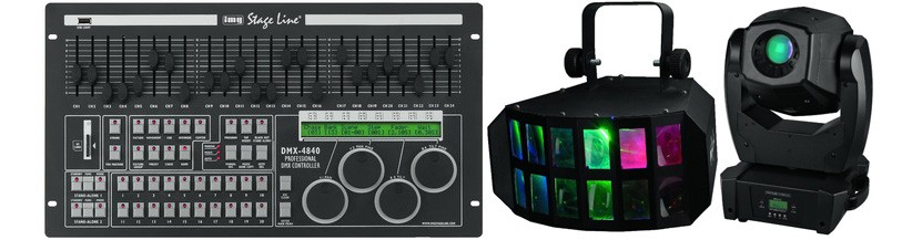
DMX Lighting Control
DMX512 is a communication protocol used to control what are commonly referred to as Intelligent Lights by universal or specific DMX controllers. DMX started out as USITT DMX512, then was abbreviated to DMX512 and is now most often called DMX
The abbreviation DMX512 stands for a Digital Multiplex Signal that can control up to 512 channels. This language was created by the United States Institute for Theatre Technology (USITT) to simplify and unify theatre lighting systems
Before DMX was created, the only lighting control system was analogue which required one individual wire to be run from the controller to each lighting fixture or dimmer pack
It is important to understand that DMX is a communication signal only and does not supply power to the lighting fixtures. All DMX lighting fixtures and dimmer packs require their own power supply
DMX is now recognized world wide as the standard communication language for theatre and night club lighting and now includes smoke & fog machines and other effect accessories
FOUR BASIC PARTS
A DMX system has 4 basic parts: A controller that creates and sends the signal, the cable that carries the signal, the light fixtures or dimmer packs that receive the signal and the terminator at the end of the control line. These are all connected in a Daisy Chain manner with the controller at the beginning of the line, the light fixtures and dimmer packs in the middle and the light at the end which also often acts as a signal terminator – if it doesn’t then a separate signal terminator will be required
CONNECTING THE PARTS
Connecting a DMX system is easy if you follow these steps:
- Link the controller to all light fixtures and dimmer packs with high quality cables
- Set the DMX address on each fixture or dimmer pack (usually, but not always necessary)
These 2 steps do not have to be done in this order, but you must not power up any part of this system until the controller, all light fixtures and dimmer packs have been connected, addressed and terminated
CABLES
It is often said… “There are MICROPHONE cables and there are DMX cables and one can NOT be used for the other”. That’s a very strong statement. Very “Black and White” and also very untrue – unless faulty either XLR mic and DMX cables can be used for DMX lighting
Here’s a few interesting facts…
- DMX was created in 1986, but not widely used or known. At that time, the popular method for transmitting signal to dimmer packs was zero to ten volts
- DMX was revised in a major way and started gaining recognition in 1990. (But not in America)
- The first DMX lighting controllers were displayed at the American LDI Lighting convention in 1999 by LitePuter
- DMX was introduced as the “Standard” digital signal for the World Wide lighting industry in 2000
Damaged cables and their connectors are the main cause of DMX system problems. Bad solder joints and corroded connector plugs can easily interfere with the signal and prevent proper operation
DMX cables should never be installed in the same conduit or junction boxes as mains or 100v line power cables. You wouldn’t even want them running side by side on a temporary basis
Never attempt to use a Y cable or splitter other than a true DMX splitter
Although a five pin XLR connector started out as the official connector for DMX, the three pin XLR connector has always been the standard in the U.S.A. and has become the most popular in the UK
Both 3 and 5 pin XLR connectors do the same thing. Pin 1 = ground, pin 2 = negative signal, pin 3 = positive signal. On five pin XLR connectors, pins 4 and 5 are usually not used
SETTING DMX ADDRESSES ON FIXTURES
Each lighting fixture and dimmer pack must have an address in order to receive data from the controller. Assigning an incorrect address to your lighting fixture is fatal – the controller will not be able to activate the fixture
DMX address mistakes are a big cause of problems with new systems and new users. Bad addresses on fixtures cause problems such as gobo change instead of mirror movement, colour change instead of gobo change, or no response at all
Download our handy DMX DIP switch app
Setting DMX addresses is sometimes very simple by following manufacturer instructions and sometimes very difficult when no instructions are available
![]()
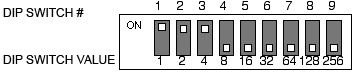
Most DMX lighting fixtures have nine DIP switches used to set the address of that fixture
Address values are easy to remember. Starting on the left and moving right, each dip switch has a value twice as large as the switch at its left
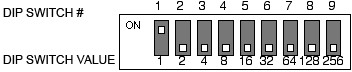
The address for a DMX lighting fixture equals the sum of the value for all dip switches in the ON position. In the picture above, the DMX Address selected is 1
Here are a few more examples…
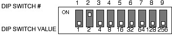
DMX Address is 2
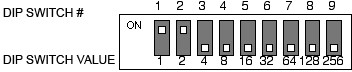
DMX Address is 3
DMX Address is 7
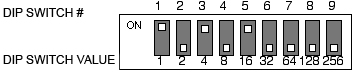
DMX Address is 21
The rule for setting an address with DIP switches is to start with the largest number of a DIP switch and work your way down through the lower numbers. To set an address of 35 you would first flip on DIP switch 6 for a value of 32, then flip on switch 2 which makes the total value now 34, then flip on switch 1 which makes the total value now 35
You might find these little switches easier to manipulate with a small screwdriver or a pen
DETERMINING DMX ADDRESSES ON LIGHTING FIXTURES
This is where the confusion starts. Many intelligent scanning lights use 4 channels; 1 for the gobo wheel, 1 for the colour wheel, 1 for left to right mirror movement and 1 for up and down mirror movement. So why does the second fixture need to be addressed 13 instead of 5? I can’t tell you why they do it, but almost all manufacturers make DMX intelligent lights that OCCUPY more channels than they USE. If you don’t have a good owners manual that clearly identifies the addresses of the second, third and fourth units, you can follow the same procedure that is used to test a new light
Connect only one fixture to the controller with only one DMX cable. Set the address of this fixture to 1. Turn the power on the controller and fixture and test each slider on the controller to identify which slider activates each item on the light fixture. After you have made a note about each slider and its activity, turn the power off for the fixture and the controller. Run a second DMX cable to one more fixture and set its address to 1. Power up all items and test the sliders again. Both fixtures should do the same thing at the same time. You can have as many fixtures as you like daisy chained together and all set to address 1. This is the simple way to test and run multiple intelligent lights
If you want to have each light doing something different from the others, you must address them each differently. This is when you need to know how many channels the light OCCUPIES. To do this, turn the power off for the fixtures and the controller. Go to the second fixture and set its address to 2. Power up all items and test the sliders again. If both fixtures don’t work properly and in sync, turn all power off and advance the address of the second unit by 1 and try again. If this still fails to operate properly, power down and advance the address of the second fixture by one again. Keep doing this until you find that the second unit works in sync with the first
If you know that your light fixture OCCUPIES 6 channels then your first fixture will be address 1, your second fixture will be address 7, the third fixture will be address 13
CONTROLLERS
When setting DMX addresses, the design of your DMX controller and each light fixtures channel function need to be observed
For instance some controllers have 12 sliders for light operations while others have 8 etc. Each is very convenient for some intelligent lighting, while inconvenient for some other lighting with fewer channels
This problem can be overcome by setting DMX addresses imaginatively – Lets say you have one intelligent scanner that uses channel 4 for left / right mirror movement and channel 5 for up / down mirror movement. You have another light that uses channel 5 for left / right mirror movement and channel 6 for up / down mirror movement. By advancing the address of one fixture, you will have the same slider controlling left / right mirror movement on both lights. You can play with the addresses of every light fixture to make sliders on your controller operate as you would like
DMX SIGNAL TERMINATION
In theory all DMX signals must be terminated – although most systems seem to work un-terminated. Termination does reduce signal errors caused by reflection at the end of the DMX daisy chain. Almost all (if not all) lighting fixtures on the market since 1999 have a built in terminator
E&OE